Customer:
Major Oil and Gas company (M.O.G)
Based upon our experience from Svend and Roar Field, but also from other production platforms in the North Sea, we know that the content of dirt and water in the hydraulic wellhead system does generally not meet the requirements and targets of the M.O.G.
Usually, the content of water in hydraulic oil is so high that free water is regularly drained from the bottom valve of the hydraulic tank. Except for this control function you never know the actual content of water in the oil in the pipe and valve system. As we are dealing with a static hydraulic system the water, which is mainly fresh water, enters with the atmospheric air, i.e. condensed water.
The objective of the M.O.G. for the level of purity in the hydraulic wellhead system is Nas 1638 class <6, and generally the level of purity of all wellhead systems lies at Nas 1638 class >7-8, which means that practically all systems contain too many impurities in relation to the objective.
Analyses of oil samples made so far show that the majority of these impurities are what we call pouring particles which means particles mainly consisting of sand, silica, polymer and fibres.
These particles get into the system with the new oil (new oil does not mean clean oil, Nas 1638 class >7) which is added to the hydraulic tank of the wellhead system without filtration, and in this way you will never obtain a purity level lower than Nas 1638 <7.
The solution: Complete Purity Control
Taking preventative measures is the first step in order to obtain a clean hydraulic wellhead system operating without problems. This is easily done when adding new oil to the tank by filtering the new oil through the off-line filter units which are already integrated in most wellhead power units.
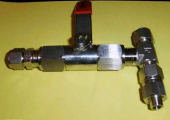
Stop the off-line pump and close the suction valve to the integrated off-line filter units and install a T-piece, ball valve, short hose and a siphon suitable for 10 or 20 litre drums with new hydraulic oil on the suction side of the pump.
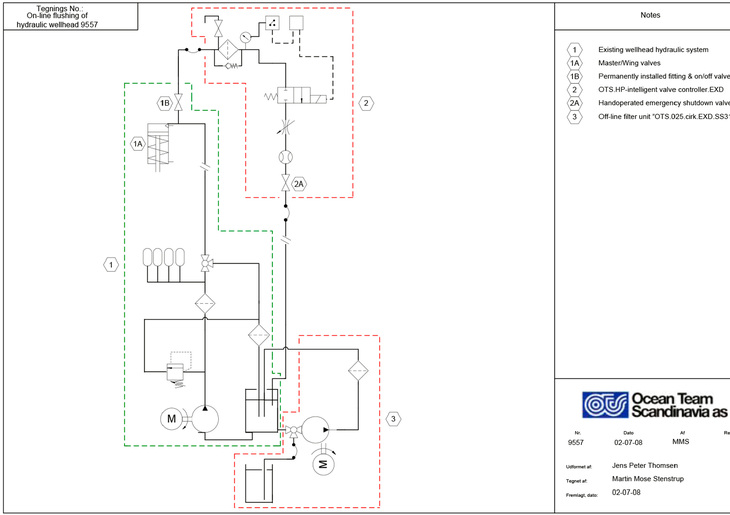
Then open for the ball valve just mounted and start the pump again. The hydraulic oil from the drum will now slowly be filled into the tank through the integrated filter. (Important to check that the filter does not by-pass the oil). When the drum with the oil is empty the pump is stopped, the ball valve is closed again, the suction valve to the tank is opened and the pump for off-line filtration can be started again. (See attached diagram pos. 3).
When the above system is installed as an integrated part of the oil filling system you can concentrate on cleaning the valve and pipe system for impurities and water right out to the X-mas trees, choke valves, ESDV’s and XCV’s.
We recommend before and during flushing to connect an off-line filter unit with 3 or 6 my beta 200 particle and water absorbing elements with a minimum flow of about 20 litres/ minute to the hydraulic tank of the wellhead system in order to be able to remove quickly and efficiently emulsified and free water and to clean the oil in the tank to required standard before starting the flushing procedure.
On-Line Pulsed Flushing of Hydraulic Pipes and Valves to the X-mas Trees HP-System: (SSSV)
The HP-system (600 bar) cannot be flushed by means of the method described above, as IKM Ocean Team standard flushing equipment cannot operate with the high pressure. Moreover oil-flushing of this system would at this stage not be relevant, as the hydraulic pilot pipe down to the valve is very long, and it would not be possible to mount a T-piece before the valve.
Apart from this, the oil in the pilot pipe would never reach back into the hydraulic tank when the valve is activated, due to the length of the pipe. Consequently, it would be the same oil flowing forth and back in the pipe when the valve is activated.
Provided that this system is clean from the start, new oil (oil with impurities) will not get into this system.
LP/MP-System:
Preparations for flushing of the LP/MP-system (approx.120 - 320 bar) is done by systematically and very shortly closing down the wells one by one. This can be done during planned closing down or under other conditions. In connection with closing down of the wells a T-piece and a ball valve are mounted on the de-pressurised wellhead hydraulic pipe just before master- and wing valve (see attached diagram pos. 1A & 1B). These preparations can be made during quite a long time in order not to disturb production.
When all T-pieces and ball valves have been mounted on all X-mas trees, choke valves, ESDV’s and XCV’s the on-line pressurised pulsed flushing process can be started. Rigging is made according to the attached hydraulic diagram, where the green colour illustrates the existing hydraulic wellhead system, and the yellow colour illustrates the provisionally mounted flushing equipment.

Short Description of the Functioning of the Flushing Method
When the hydraulic system is under full pressure (about 120 - 320 bar) a signal is given by the pressure gauge of the automatic valve (pos. 2) to a timer function which allows a certain time for the system to get stabilized.
After elapsed time, the timer gives a signal to the actuator to open. The oil will now with very high velocity R>3000 flow through the loop-filter (pos. 2) and back into the tank. As the accumulators (pos. 1) are emptied, pressure will drop, and this pressure drop (max. 55 - 250 bar) is registered on the pressure gauge of the automatic valve and makes the actuator close immediately. The system will now begin rebuilding a pressure in the accumulator and the system. Upon completion the process is repeated until oil samples taken regularly show that the system is now clean.
Comments:
After completion of the oil-flushing operation of the hydraulic wellhead system of Svend and Roar Field in the North Sea, which was carried out by means of turbulent pulsation without disturbing production, we can modestly ascertain that the above flushing procedure was successful.
The purpose of carrying out the above flushing procedure on all hydraulic wellhead systems is to secure/guarantee total purity (Nas 1638 class <5) and no water in the whole system from the hydraulic pump to power unit through the wellhead drawers and out to master- and wing valve on the X-mas trees as well as choke valve, ESDV and the XCV’s, and in this way to secure/guarantee increased reliability and reduced operation and maintenance costs. The result obtained through this procedure is characterized by establishing pulsation while the oil is still a part of the technical process. A characteristic advantage of this system is that no expensive installation work is required to carry out cleaning. The system and method is patented by IKM Ocean Team Scandinavia A/S.
