Customer:
Major Oil & Gas company
The System:
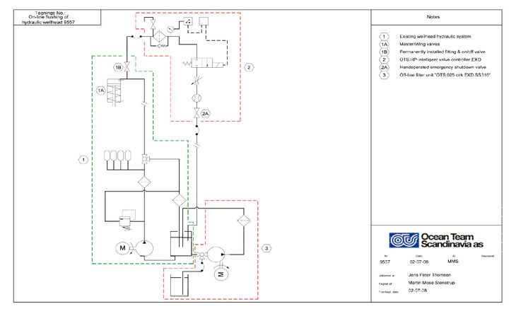
General analysis of the condition of the hydraulic wellhead system before flushing
Based upon our experience from Skjold, Dan, Tyra East and West and a number of satellite production platforms in the North Sea, we know that the content of dirt and water in the hydraulic wellhead system does generally not meet the requirements and targets of our customer.
Water and Dirt in the Oil
Usually, the content of water in the hydraulic oil is so high that free water can regularly be drained from the bottom valve of the hydraulic tank. Except for this control function you never know the actual content of water in the oil in the pipe and valve systems. As we are dealing with a static hydraulic system, the water, which is mainly sea water, enters into the system through one or more leakages from either the hydraulic control lines or from the SSSVs.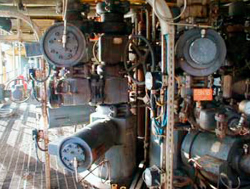
The objective of our customer, for the level of purity in the hydraulic wellhead system, is Nas 1638 class <6, and generally, the level of purity of all wellhead systems lies at Nas 1638 class >7-8, which means that practically, all systems contain too many impurities in relation to the objective.
Oil Analysis
Analysis of oil samples made so far, indicate that the majority of these impurities are what we call pouring particles, meaning particles mainly consisting of sand, silica, polymer, and fibres. These particles get into the system with the new oil (new oil does not mean clean oil, Nas 1638 class >7) which is added to the hydraulic tank of the wellhead system without filtration and this way you will never obtain a purity level lower than Nas 1638 class <7.
The Solution
In the light of the above analysis of the condition it was decided to carry out IKM Ocean Team’s patented on-line pulsed flushing operation on all wellhead panels on the above platforms. IKM Ocean Team has carried out these operations during the last 3-4 years.
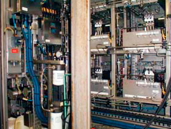
Upon completion of the oil-flushing operation of the hydraulic wellhead system on the above platforms, an operation which was carried out by means of turbulent pulsation without disturbing the production, we can modestly ascertain that the above flushing method was a success.
 .
.
The purpose of carrying out the above flushing procedure on all hydraulic wellhead systems was to secure/guarantee that the system is completely clean (Nas 1638 class <5) and free from water, right from the hydraulic tank, pump, through the wellhead drawers (SOV’s) and all the way to the master- and wing valves of the Xmas trees as well as the choke valve, ESDV and XCVEs, in order in this way to obtain certainty/security concerning an increased reliability as well as reduced operation and maintenance costs.
Added Bonus
Moreover the flushing method turned out to have an added bonus, as the closing time of most wells has obviously been too long, and after the flushing it turned out that the closing time of around 90% of the wells had been considerably reduced; this must be described as a significant added bonus together with a clean hydraulic system. This success with reduced closing time has more or less removed focus from the purpose of the flushing, i.e. to obtain a clean system. I would not say that these things are not closely connected.
In far the most cases of long closing times it has helped to condition the solenoid valves either mechanically (which, however, means closing down the well) or by means of on-line pulsed flushing. It has turned out, that the sleeve valve of the solenoid valve (SOV) has obviously developed a certain degree of sluggishness and consequently the oil can only pass through slowly which makes the well close slower than usually.
The Question is – what Caused this Sluggishness of the Sleeve Valve?
We have received a number of reasonable answers and theories concerning this phenomenon, for instance that the magnetic spool has been with current so long time that the shaft has been magnetized which makes the sleeve valve remain in its position for some time after current has been interrupted. Alternatively, the power of the spring is reduced after long time of tension. Our theory is – and has been all the time – that the sluggishness is caused by dirt getting stuck in the tolerance area between the sleeve valve and the cylinder valve. Caused by the pulsations during the flushing these particles of dirt are torn loose and led to the flush filter. This will reduce the friction resistance in the valve and increase the flow speed of the oil, which again explains the shorter closing times of the wells.
A new Problem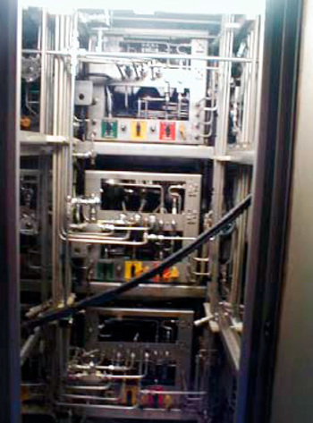
It has, however, later turned out that the closing times of some of the wells became longer again after a relatively short period. The definition of a short period means here that at Skjold Field they registered some wells with longer closing times approximately one year after flushing, and at Tyra West and East Field one single well showed increased closing time only few months after flushing. This is naturally sensational and worrying at the same time, as during normal operation the system should not generate particles so fast, and you could be inclined to believe that the system was not completely clean after the flushing operation.
After our customers Discipline Engineers has explained this problem to me I have done some research and I have now reached a completely new theory which leans against the old one but with another formulation of the problem.
It actually seems that micro organisms in oil are similar to bacteria, and the risk of growth of micro organisms in the oil seems to be considerably higher than before, as most oil products today more or less have to meet the new requirements as to environmental protection. For this reason lubricating oils become more and more like a basic oil due to less addition of additives, and this means that lubricating oils become less resistant against microbiological organisms/bacteria, especially in places where sea water is or has been in the system (see article from Norwegian College of Agriculture, NI Institute for Biotechnology by Jon F. Hansen or www.fras.com/ technicalnews/270.asp).
The size of these micro organisms usually lies between 1 and 3 my, and they are consequently smaller that the filter size of a 3 my Beta 200 filter element. These particles are in other words being washed through the filter, and can therefore not be removed be ordinary inline system filtration.
The residual products (colloquially called oxidation residues/varnish) from this microbiological growth are a visual grey/brown mass (viscosity like snot) which is mainly visible for the eye at the bottom of the hydraulic tank. This mass will stick to all stationary surfaces and after some time it will become almost like resin. As the wellhead and the ESDV hydraulic systems are static (i.e. stagnant flow) contrary to ordinary hydraulic systems, which are dynamic (i.e. flow in circulation), there is a much higher risk of these resin-like sediments in components and pipes than in ordinary hydraulic systems.
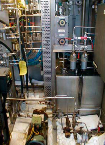
Oxidation Residues are Generated in Non-Flow Situations in Tank, Pipes and Components, and will Cause Sluggishness especially in Valves (SOV).
This means that the resin in non-flow situations has good possibilities of growth, for instance in the tolerance area of the solenoid valve between the sleeve valve and the cylinder valve. The viscosity of the resin is strong enough to cause sluggishness of the valve when activated.
Solution of the problem: One of the more safe solutions, which will not disturb production, is offline filtration by means of pot filters for absorption of water and particle filtration. These filters make what we call depth filtration which means that the oil is to pass through a filter structure which is very thick compared to ordinary inline filters, and moreover the element is made of cellulose. The pot filter is characterized by the very low flow velocity which has the advantage that very small particles as for instance oxidation residues are not washed or flushed through the filter element but are stopped at very low speed in the web of the filter and get stuck there because of the cellulose which almost has the same effect as glue on the particles.
However, this advantage of the low flow velocity is, in this case of static systems, also a very large disadvantage, as circulation in the hydraulic tank (with bad design as must wellhead hydraulic reservoirs is) is made only by the pot filter offline filter unit, and considering the low flow this is not sufficient to represent the whole area of the tank. The flow from the filter unit will create a small, clean track through the tank, where the filter is drawing until it is re-turned to the tank. The remaining area of the tank still has good growth possibilities for bacteria. Moreover offline filtration will not solve the problem in pipes and components. Another possibility is biocide injection to the hydraulic oil in order to kill the bacteria growth. (See article from www.fras.no/news/3545.asp).
I have been talking to Hydro Texaco technical department concerning this way of solving the problem. Their opinion was that this solution is an uncontrollable symptom treatment in the long term and cannot be recommended. There will be a problem with removal of the dead cells from the micro organisms and possibly environmental problems in connection with handling of the oil offshore, compare HOCNF (OSPAR Desions 2000/2).
A third possibility is to condition the sleeve valve of the solenoid valves (SOV) mechanically or by activating the valve either electrically or pneumatically at regular intervals in order in this way to prevent the formation of resin in the tolerance area thus causing sluggishness of the valve. This will, however, mean closing down of the wells during the conditioning of the valves i.e. operational interruptions.
Finally, a fourth possibility is to work in a procedure for routine maintenance of the oil as a component by means of on-line pulsed flushing. All hydraulic master/wing valves should then be connected with T-pieces and valves to the control line which makes it possible to connect the flushing equipment in an easy and accessible way without interrupting production. Apart from the above advantage this method would mean that the micro organisms will be flushed out from pipes and components at high velocity and back to the hydraulic tank. This flow in the tank will form a circulation and movement in the tank (dynamic) which will lift the bacteria growth up from the bottom and part of the flow will go through the pot filters offline filter unit along with the particles being flushed through the filter. This method might not be the most economic solution at short sight, but at long sight this solution could secure continued control and operation without interruptions.
