- It is possible to change oil and carry out flushing of static hydraulic systems without shutting down systems, by a patented method developed by IKM Ocean Team.
This results in massive savings as production can be maintained during the operation.
Shutting down production is no longer necessary to carry out change of oil or flushing of static hydraulic systems. Shut down of especially offshore ESDV and well head systems is very costly due to expensive loss of production.
Consequently, IKM Ocean Team has developed a specific method which makes it possible to change and clean the hydraulic fluid in exactly these central systems without shutting down production.
Disadvantages by Using Alternative Methods
Basicly the following three phases are necessary when replacing an existing hydraulic fluid by a new and more eco-friendly fluid:
- Drawing the existing fluid from the system.
- Cleaning of the system in order to remove remains of the old fluid and other impurities.
- Filling up the new fluid.
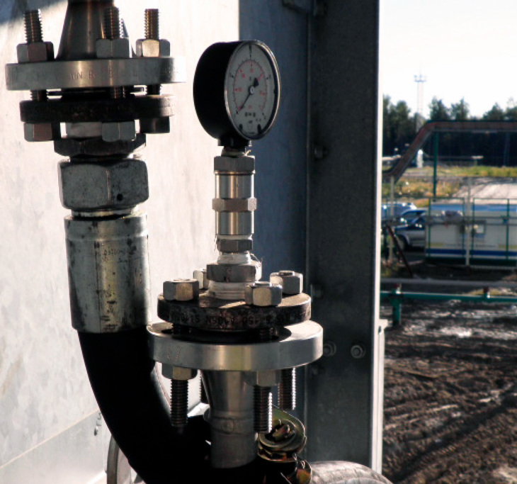
Shut down of systems are costly due to loss of production
Two different fluids being mixed together may have severe consequences for the reliability of the system. Consequently, cleaning to remove remains of the old fluid as well as other impurities on the inside of the hydraulic system forms an essential part of the process of conversion.
Such cleaning can be made in many ways. A common and efficient method is to expose the hydraulic fluid to pulsations in order to create a strong and turbulent flow inside the hydraulic system. This turbulent flow will loosen the old oil and other impurities on the inside of the pipes. The unwanted particles are carried out from the system by the turbulent hydraulic fluid and are finally being passed through a filter.
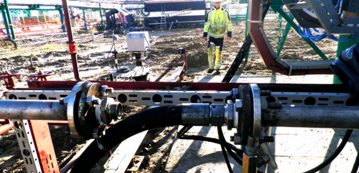
Maintain the technical process while flushing and replacing hydraulic fluid
To carry out this cleaning process, called flushing, you use a plant which is successively connected to the hydraulic system at different places until the whole system has been cleaned.
However, the disadvantage by using this common method for flushing is that the hydraulic system cannot be involved in other technical processes during flushing. In other words you will have to shut down the system.
Shutting down the system will not be an expedient solution when dealing with static hydraulic systems as ESDV and well head systems, as the general flow of production is dependent on continuous operation of these systems.
Such systems require more innovative solutions which eliminate the need of shutting down production during the processes of conversion and flushing.
IKM Ocean Team Has the Solution
IKM Ocean Team has developed a patented method which makes it possible to maintain the technical process in the production plant along with flushing of and replacement of the hydraulic fluid in the static hydraulic system.
The Following Phases Form the Process:
- Preliminary study; before the execution of each job a thorough preliminary study of the system concerned is made in order to identify any possible reservations. After this the technical work description is worked out and adapted to the specific job in question.
- Mounting; a temporary tank and pump are connected to the existing hydraulic system. During the whole process this temporary pump is used as the primary system pump whereas the existing pump works as backup. In this way the original system pump is being spared from unnecessary wear and stress as a consequence of the conversion and flushing.
- Draining off and mechanically cleaning the oil reservoir; the oil reservoir of the hydraulic system is disconnected from the system and replaced by a temporary tank containing the existing hydraulic oil. At the same time the return pipe to the oil reservoir is by-passed and led into a temporary drain/waste oil tank, which will remain in operation during the whole process of conversion.
The hydraulic system continues its ordinary operation by using the temporary tank, while the oil reservoir is drained off and cleaned mechanically. Finally, the reservoir is filled with the new hydraulic fluid. - Conversion of oil and preliminary flushing; the original mineral oil is now gradually replaced by the new hydraulic fluid. By means of pulsations a turbulent flow is created which makes the new fluid gradually press out the old oil from the hydraulic system. This process is explained in details below.
- Current oil analysis and pressure measurement; the whole process is carefully supervised by current oil samples and pressure measurements. The oil samples are taken in order to follow when the fluid in the hydraulic system has been converted to the new fluid.
This is done by comparing measurements of the individual substances in the old fluid with measurements of the new fluid. In this way it is possible with a high degree of certainty to check when the fluid has been converted. The combination of substances varies from one fluid to another.
Diagram 1
Development in Pressure Balance during Online Conversion of Oil and Pulse Flushing
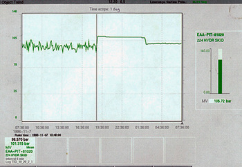 The diagram shows a print from the monitor in the control room (CCR) during the execution of online pulse flushing of an ESDV system.
The graph to the right shows the controlled variations of pulsations in the pressure balance of the ESDV system, which occurs during an online conversion of oil and pulse flushing.
The pressure of the system varies between a carefully monitored minimum and maximum level which makes it possible to maintain ordinary production along with the execution of conversion of oil and flushing of the ESDV system.
Diagram 2
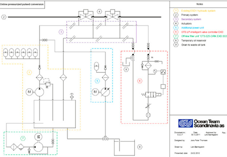
Drawing showing the principles of online conversion of oil and pulse flushing of ESDV systems.
6. Final flushing; when the hydraulic fluid has been converted all over the hydraulic system a final flushing is made to ensure a proper degree of purity.
7. Control of oil analyses; oil samples are taken for analysis to check the degree of purity according to ISO 4406, ISO 4407 or NAS 1638.
Composition of the Conversion Plant
The above diagram 2 shows the principles of an online conversion process in an ESDV system. The diagram shows the components which are to be mounted on the hydraulic system to carry out the conversion.
Positions marked 1 and 3; represent the existing hydraulic ESDV system (the secondary system). Position 2 is the existing processing system (the primary system) and position 4 is the actuators of the processing system. Position 5 represents a temporarily connected power unit. The latter has been connected to the system for two reasons: It stands as back-up for the existing system pump in order to avoid shutdown if the system pump for some reason should fall out. Moreover, it creates a stronger flow in the hydraulic system which means that pressure in the accumulator can be built up after pulsation in less time.
Position marked 6; is an automatic valve. The purpose of this valve is to control the quantity of fluid which is led out from the system and into a drain/waste oil tank (position 9) without lowering the general pressure in the hydraulic system too much. In order to be able to pulse a reasonable quantity of fluid from the system without a quick reduction of pressure it is necessary to mount an accumulator with plenty capacity. This is integrated in position 5.
Position marked 7; is an offline filter unit connected to the system tank to secure the level of purity in the new fluid which is added to the hydraulic system.
The process of conversion is followed up by a final flushing. In principle the same procedure as for the conversion is used. The difference is that now we do not drain off fluid but instead the new hydraulic fluid is led through extra filtering units connected and then back into the hydraulic system in a recirculation loop until the required degree of purity has been achieved.
Conversion of oil and flushing of hydraulic well head systems will principally be made after the same method as for the ESDV systems. However, the composition will look different – see diagram 3. It should be mentioned that the exact technical process description can only be made after a site visit where the system in question is being checked for possible reservations.
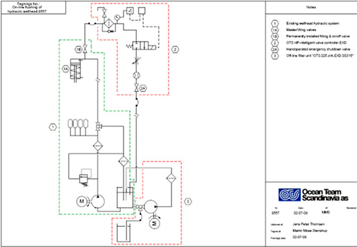
Diagram 3; Drawing showing the principles of online conversion of oil and pulse flushing of well head systems.
How Does the Method Work?
In short, the pressure balance of the hydraulic system is exploited to create turbulent flow by means of pulsations. A short description of the method is given below:
When the hydraulic system has reached full pressure a signal is given from the pressostate of the automatic valve to a timer function which allows a certain preset time for the system to stabilize. When the time has elapsed the timer sends a signal which opens the automatic valve.
The old oil will now at a very high speed (Reynolds figure (R) more than 3.000) run out of the hydraulic system and into a temporary drain/waste oil tank. This will cause a controlled loss of pressure in the hydraulic system, which will be registered by the pressostate of the automatic valve.
As soon as the loss of pressure reaches a fixed minimum level the automatic valve will immediately close again. Subsequently, the hydraulic system will again start building up a pressure. When the pressure reaches the fixed maximum level, the automatic valve will open again. This process will be repeated until the old oil has been replaced by the new hydraulic fluid. During the whole process pressure is maintained in the hydraulic system which is necessary for the system to be part of the technical production process at the same time.
Safety
Safety, monitoring, and control are essential factors in order to secure personal safety and reliability in operation during the whole process. For this purpose there will be continuous radio contact between IKM Ocean Team’s technicians and the control room (CCR). This is meant to ensure that everybody knows where in the system the technicians are situated and what they are doing. It also makes it possible to contact them in case irregularities should occur during the process.
Before starting up a conversion process it is important to check that the new hydraulic fluid is compatible with the individual components of the hydraulic system.
This is necessary to secure that reliability in operation can maintain during as well as after conversion. As the customer chooses the new hydraulic fluid he will be responsible for checking this as well.
Financial Advantages
The advantages connected to the application of this method for online conversion of oil and flushing of offshore hydraulic systems are remarkable:
- No loss of production; the operation is made online along with the normal operation.
- Totally cleaned system; the system is being cleaned for all remains from the old oil and other unwanted particles.
- Safety for obtained level of purity in the new hydraulic fluid; by means of offline filtration in connection with filling the new fluid to the system combined with regular analyses of oil samples.
- Increased reliability in operation; a high degree of purity directly results in increased reliability in operation as well as reduction of the general costs for operation and maintenance.
- Flexible equipment; which does not require extensive installation work.